1963 Ford 4000 Manual Steering Gear Box Exploded View
< PREV Page NEXT Page >
A1
Removing gearbox

Special tools and workshop equipment required
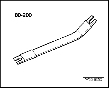
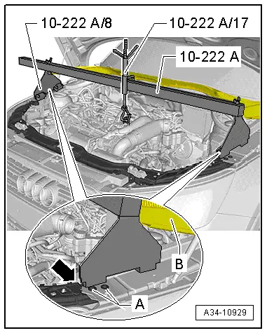
| t | Support bracket -10 - 222 A- |
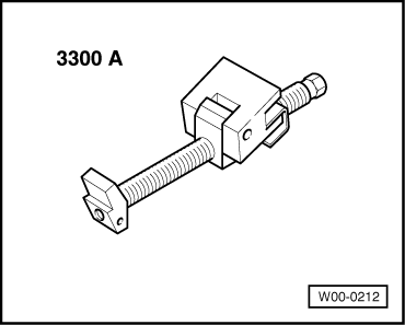
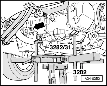
| t | Gearbox support -3282- |
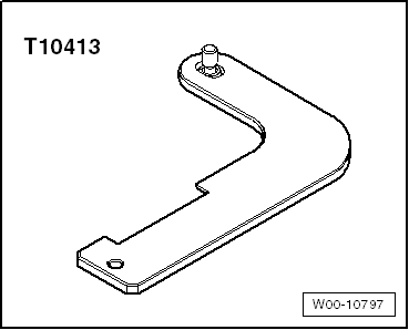
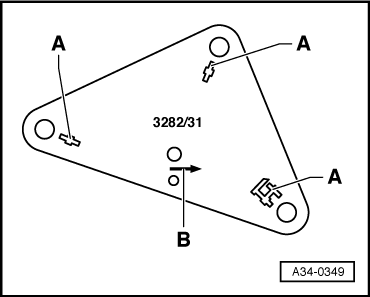
| t | Adjustment plate -3282/31- |
| t | Engine and gearbox jack -V.A.Thousand 1383 A- |
|  |
|  |
|  |
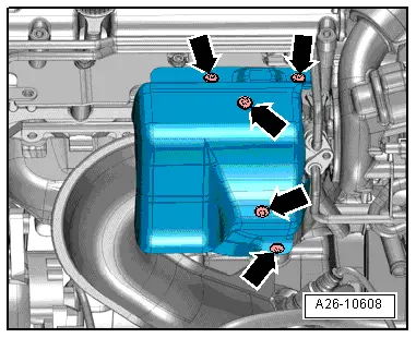
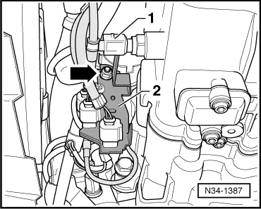
| Procedure Re-adhere all cablevision ties at the aforementioned locations when re-installing.
|  |
 Note
Note
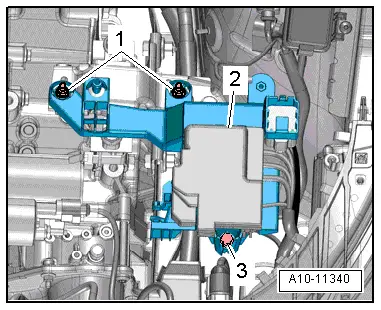
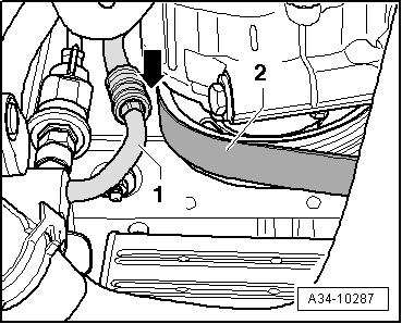
-Detail 2- tin can be overlooked. | 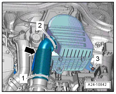 |
When disconnecting the battery at that place is a gamble of serious damage to electronic components: Observe the correct procedure for disconnecting the bombardment. | 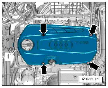 |
 Caution
|  |
|  |
|  |
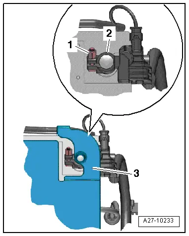
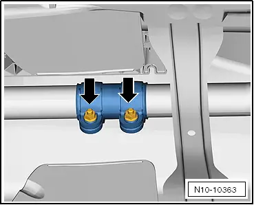
Run a risk of irreparable impairment to clutch slave cylinder. Practise not press clutch pedal after removing clutch slave cylinder. | 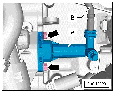 |
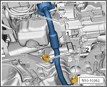
| Vehicles with starting time/stop organization:
Continued for all vehicles: | 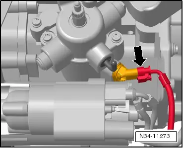 |
| 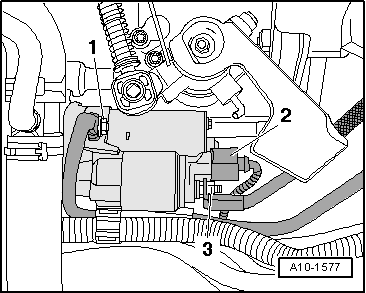 |
-Item ane- and -detail 3- can exist disregarded. | 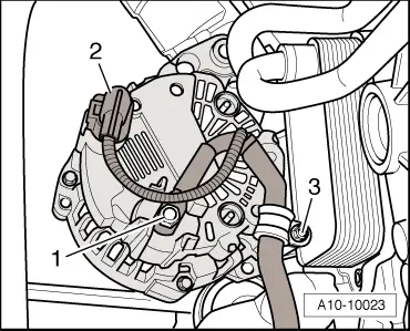 |
|  |
|  |
|  |
|  |
|  |
|  |
|  |
|  |
|  |
|  |
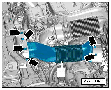
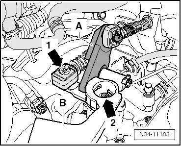
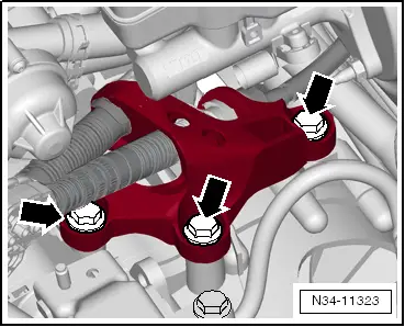
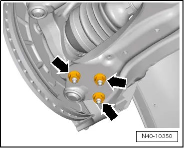
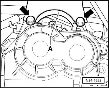
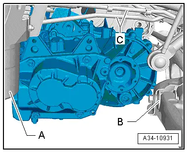
| Hazard of accident. The bolted connectedness -1- must not be slackened.
| 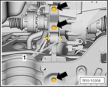 |
 WARNING
|  |
|  |
|  |
|  |
|  |
|  |
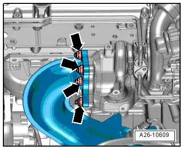
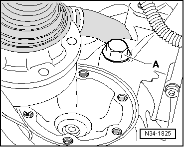
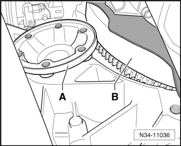
Place flat safety cake -pointer- between the 2 to protect sump.
|  |
|  |
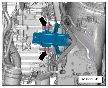
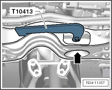
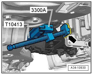
| To remove gearbox „02U", set up gearbox support -3282- with aligning plate -3282/31-.
|  |
|  |
|  |
|  |
< PREV PAGE Side by side Folio >
DOWNLOAD HERE
1963 Ford 4000 Manual Steering Gear Box Exploded View UPDATED
Posted by: ronaldusbal1959.blogspot.com


0 comments:
Post a Comment